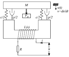
Fig 5.14: An electromagnetic circuit
Direct current magnets have found a wide range of applications, as actuating elements in devices with automatic control, in precision mechanics, etc. Latest applications of these magnets have set more rigorous requests with regard to increase of the switching speed and dimension miniaturization. It is very important to model and simulate electromagnets, in order to optimize their parameters. Especially important is transient analysis, where the goal is usually to find the optimal waveform of the input voltage in order to obtain fast switching of the armature, but to avoid damage of the contacts caused by collisions.
Fig 5.14: An electromagnetic circuit
Schematic representation of a DC magnet is shown in Fig. 5.14. Position of the electromagnet is determined by the equilibrium of mechanical and magnetic forces:
![]()
Mechanical force is a sum of four components. These may be expressed as shown in Table 5.2.
Notation used here is: M for mass, c for spring constant, ρ for friction resistance.
Table 5.2: Mechanical forces acting on the armature.
Total mechanical force is then:
![]()
The value of the magnetic force depends on electrical quantities. Electrical part of the device can be modeled as:
![]()
where R represents ohmic resistance of the coil, and ψ is the magnetic flux. The flux is determined by the current through the coil and the size of the air gap between the movable armature and the magnet core.
![]()
Magnetic force can be than calculated as:

where Emag denotes electromagnetic energy in the air gap.
The equilibrium equation (1) can now be written as:
![]()
Equations (5.6) and (5.9) represent the model of the magnet that should be implemented in an HDL. Unfortunately, function that determines flux is, as is already mentioned, usually very difficult to obtain in a closed form. An artificial neural network (ANN) can help solving this problem. We used ANN shown in the Fig. 5.15 to approximate flux as a function of i and x. Moreover, neural network can be used to calculate directly g(i,x), i.e. the magnetic force. Force is the function of the same inputs i and x, and the same network calculates both values. For that reason, network in Fig. 5.15 has two output neurons. Both values are necessary for implementation of the model in the simulator (equations (5.6) and (5.9)).
Fig. 5.15: ANN used in modeling magnetic characteristics
As mentioned in section 3.2, AleC++ have special operators for description of first and second order time derivatives. The latter one was developed particularly for description of mechanical systems, since second order differential equations are often in use there. For that reason, eqn. (5.9) can be described nearly as it is given in the text.
main_equation: process per_moment {
eqn x: -{Fmag} +M*d2dt2{x} +RO*ddt{x} +c*{x} = -F0;
}
For the voltage excitation the step function is used. Its amplitude was 24V. All variables (x(t), v(t) and a(t)) were considered zero for t=0. In Fig. 5.16(a) the simulation results are given. As may be seen, the movable part of the core eventually reaches its goal with significant velocity. These results are to be compared with measured ones given in Fig. 5.16(b).
Fig. 5.16: (a) Simulation results. (b) Measured characteristics